Vector Math is Not the Tool of Satan
October 4, 2001
by Paul Catanese
So, you've been programming 3D in Director for a few months now and everything has been going relatively well. But you have this nagging question: what the heck do you use the dot product and cross product functions for? You've read the help file entries ten times and you can recite "dot product returns the cosine of the angle between two normalized vectors" like some sort of mantra; but you still feel like that leaves you sitting on your faith.
In this article, I am going to show you a technique that makes use of vectors, normals, normalization, the dot product, the cross product and vector subtraction processes. Specifically, I will be showing you a custom function for the purpose of determining whether a given 3D point is in front of a plane, behind a plane, or on the surface of a plane. Let's start by taking a look at this technique in action in the following Shockwave movie:
In this example, you can use your mouse to either drag the box around in 3D space, or you can rotate the plane in all directions. Just click and drag to get a feel for the interface. Looking closely at the plane, you can see that there are a few primitives that I have attached to the plane: a green cone which represents the direction of the normal from the plane and three red spheres which represent three points on the surface of the plane. When the box is on the side of the plane that the cone points toward, the box is colored blue, when it is in the opposite half of the environment, the box is colored yellow.
In this example, although the plane is small, I am using it to represent an infinitely wide plane that divides the 3D space into two discreet sections, or half-spaces. Often, these half-spaces are referred to as "inside" and "outside". For this reason, the technique that we are looking at is often referred to as an inside/outside tester. It is an extremely robust tool that has applications in performance optimization and autonomous agent control among many other areas of 3D programming.
Terminology
In order to begin, we must be sure that you understand several givens about working with vector mathematics this way the terminology will not hamper your understanding of the technique.
- Vector
- A vector is both a mathematical concept and a data type in Director. In terms of math, a vector is an important construct that has both a direction and a magnitude. It is often useful for physicists to use vectors to represent natural forces. InDirector, vectors represent a direction and magnitude. They are comprised of three components: X, Y, and Z. Often, users will assume that the X, Y, and Z components refer to a specific location in space. This is not entirely true -- you should always think of a vector as a displacement in space, a change from one place to another. The data that vectors represent is dynamic.
Scalar- A scalar is a regular number that only represents a single value (where a vector represents two values).
Direction Vector & Location Vector- Often, vectors are referred to as location vectors or direction vectors. This does not change the fact that these vectors have both a location and direction, it just means that in the context that the vector is about to be used, only one or the other value is going to be important.
Normalized Vector- Normalization is a process that divides each component of a vector by the magnitude of the vector. The result of this process is a vector whose magnitude is 1, but whose direction remains the same as the original vector. Normalized vectors are sometimes referred to as direction vectors, or unit vectors.
Plane- An infinitely thin, infinitely wide geometrical construct that can be defined by any three points that are non-collinear (not on the same line). A plane can also be defined with two lines, or two vectors. In Director, the plane is also a type of modelResource which does have finite dimensions -- in this example, I am talking about the former, although I am using the latter to help you visualize the plane used to divide the 3D space into half-spaces.
Normal- A normal is a vector (not necessarily normalized) that is perpendicular to two intersecting, non-equal vectors (which define a plane). A vector that is perpendicular to two vectors that define a plane is also a normal to the plane. For each plane, there are two possible normals that point exactly opposite one another. No matter the position of the plane in 3D space, there will always be two normal vectors that are perpendicular to the plane. One will point towards the "inside" section of half-space and the other will point towards the "outside" section of half-space. It is going to be our job to make sure that we refer to the right one.
Vector Subtraction- The result of subtracting two vectors is a third vector. Vector subtraction is not commutative; this means that the order of operands is important. If you reverse the order of operands, your result will be different.
Dot Product- The dot product is one of two methods for multiplying two vectors. When you use the dot product on two vectors, the result is a scalar. If the two vectors are normalized prior to the dot product operation, the scalar result will be between -1 and 1, and will be the cosine of the angle between the two vectors.
Cross Product- The cross product is the second of two methods for multiplying two vectors together. When you use the cross product on two vectors, the result is another vector. That vector is the normal to the two operand vectors. The cross product is not commutative; if you reverse the order of operands, the result will not be the same. The result will have the same magnitude, but it will point in the opposite direction!
The Process
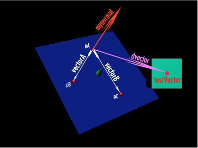
In Figure 1, I have labeled the various features that play a role in this example so that it will be easier to explain the process and the code. The steps for building an inside/outside tester are as follows:
- Given three location vectors pA, pB, and pC that represent points on the surface of a plane, we can use vector subtraction to generate two vectors (vectorA and vectorB) whose magnitude and direction define the plane in 3D space.
- With these two vectors (vectorA and vectorB), we will use the cross product to find the normal of the plane, which we will call myNormal. We are mostly interested in the direction of myNormal, so we will normalize it.
- Our next job is to use vector subtraction to generate a vector from any point on the plane to the point we are trying to determine the status of. We will call this dVector. We are only interested in this dVector as a direction vector so we will normalize dVector as well.
- We will calculate the dot product of myNormal and dVector -- essentially, myNormal.dot (dVector). Because both of these vectors are normalized, the dot product will be the cosine of the angles between the two.
- If the dot product equals zero, the point is on the plane. If the dot product is greater than zero, the point is on the side of the plane opposite the direction of the normal. If the dot product is less than zero, the point is on the side of the plane in the same direction as the normal.
The Code
on inOut(pA, pB, pC, testVector)
global scene
-- determine the vectors between pC - pA
-- and pB - pA.
vectorA = pC - pA
vectorB = pB - pA
-- solve the cross product, which will return
-- the normal of the plane
myNormal = vectorA.cross (vectorB)
-- normalize this result
myNormal.normalize ()
-- determine the vector between testVector and any
-- point on the plane. In this case, I will choose
-- pA, since we know that it is on the plane.
dVector = testVector - pA
-- normalize dVector
dvector.normalize ()
-- solve the dot product of the normal and dvector.
-- because these two vectors have been normalized
-- the result will be the cosine of the angle
-- between these two vectors
testresult = mynormal.dot (dvector)
-- check to see if the point in on the plane,
-- in back of the plane, or in front of the plane.
if testresult = 0 then
return #onPlane
else if testresult > 0 then
return #inside
else if testresult < 0 then
return #outside
end if
end
Using the Custom Function
Before you rush off with this function, I would like to run through how to actually use it. It is important to understand what the arguments represent in order to be able to interpret the results of the function accurately. You know that you will call the function with something similar to the following:
Testresult = inOut (pA, pB, pC, testVector)
It should go without saying that each of the four arguments are vectors in world coordinates. The first three vectors represent points on the plane that divides 3D space and the last vector represents the point that you are testing the position of in relation to that plane. It is important that you understand that it is not good enough to simply find three points on the plane and then arbitrarily assign them to pA, pB, and pC. Why? Because, the order of pA, pB, and pC determine which side of the plane is "inside" and which is "outside". Take a look at the following figure:
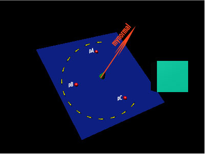
In this figure I have designated that pA, pB, and pC are assigned in counterclockwise order. When I call inOut and pass the points in counterclockwise order, the "inside" is as you see it in the diagram -- if I reverse the order which the values for pA, pB, and pC are passed, then "inside" will be defined as the opposite side of the plane.
This custom function has been set up to return three different symbols: #onPlane, #inside, or #outside depending on the position of the point. You would most likely use the results of this custom function in a case statement or multiple case statements in order to determine what to do with the information returned.
Conclusion
While in this example I have made use of a plane, a cone and some spheres to illustrate my point, they are not necessary. While it is easiest to conceptualize generating world coordinates from models in a world, you can just as easily use transform objects to store positions, or dummy models (models without modelResources). The possibilities are extremely wide, and I will leave the specific implementation of this custom function up to you.
I will say that partitioning 3D space is a powerful tool that can be used in a wide variety of circumstances. Although in this demonstration we have only divided 3D space into two halves, it is possible to divide the space multiple times. With conditional statements it is possible to inform the logic engine end of your projects about complex relationships between models and locations within the 3D environment.
Some possible uses for this technique include determining which sections of a 3D environment to remove from the world when not in use, when to download extra sections of an enormous 3D environment or when to allocate more or less processor time to code that runs autonomous agents. An extended explanation of this demonstration and its concepts appear in Chapter 26, "Vector Math and Advanced Transforms" of the book Director's Third Dimension: Fundamentals of 3D Programming in Director 8.5.
Copyright 1997-2026, Director Online. Article content copyright by respective authors.