LingoLand: Simple 3D Terrain Simulation in Lingo, Part 1
April 17, 2001
by Andrew M. Phelps
[Editor's Note: While this article deals with 3D in Director, it doesn't specifically address the Shockwave 3D technology in Director 8.5, announced by Macromedia last week at the User Conference. So you might ask: "Why is DOUG publishing it?" There are a couple of parts to that answer. Until you've got Director 8.5 in your hot little hands (and you can expect your clients to be able to view it), you'll still need to find other ways of working in 3D if you need it. The underlying theory in basic 3D is just as relevant now as it ever was; one of the model primitive types in Shockwave 3D is the mesh, which makes great terrain. -DP]
This article describes the implementation of a simple terrain generation system in Lingo. This material was used to teach the basics of lists and objects at the Rochester Institute of Technology to a graduate class of students pursuing a Multimedia Programming track. As such, while it implements a fully-featured 3D engine, the engine is not optimized to its fullest extent, and the data structures used are the most logical, not necessarily the fastest. Optimization techniques will be discussed at the end of this document, and references given to faster simulation environments written in Lingo.
In spite of this focus, the engine does perform soundly, offering implementation of traditional computer graphics approaches to rotation, translation, and scale as well as basic lighting. Additionally, it offers a trails-based solution to overcome the limitation of the upper limit of a thousand sprites in Macromedia Director. Finally, this engine could very easily be combined with the file-saving system presented by this author on another project [Phelps, February 2001] and is also used as a simulation environment for experimentation with artificial life and genetic algorithms within the Director framework [Phelps & Kunkle, forthcoming]
3D Engine Implementation
Tutorial File Setup
Terrain simulation has been a long-standing issue in the computer graphics community, with applications ranging from simple game worlds to advanced applications that simulate terrain based on large data sets like those produced by satellite mapping. This project seeks to implement none of that complexity. Instead it is concerned with rendering a very simple, randomly-generated terrain, controlled by a few simple variables that are set by the user, primarily for students writing their first simulation environment.
The first thing to do is download the files associated with this document and open the Director movie. Play it. Click the Make Land button until you get one you like. Experiment with moving the light around. Click the Subdivide Surface button, and watch as it divides the surface to display at a finer resolution. You should see something like the screen depicted in Figure 1, although your actual results will depend on light placement and the original terrain, which is random.
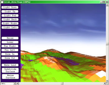
Figure 1. Terrain with 4 subdivisions.
View the terrain generator movie.
Next, you can achieve very different effects by creating the random land point generation at a subdivision level other than '1'. To accomplish this, restart the movie if necessary, click the Subdivide Surface button, and then click Make Land. Note that the engine will create the new land at a higher level of detail, producing a more turbulent surface. Finally, experiment with the global variables that control the simulation to get a feel for how the engine works and its capabilities. These variables control the way that the engine performs, and the type of land that is produced. A table listing these values is provided for reference in Table 1.
Table 1: Engine Control Variables
| Variable | Description |
| max_row, max_column | The size of the original land matrix. This is the number of 'points' in X and Z that you see the original land created with when the movie starts. |
| square_size | Size in pixels of the original tiles, the space between the points defined above. |
| min_height, max_height | The minimum and maximum heights allowable for random generation of land elevation. Values closer together will produce rolling hills, disparate values produce mountainous regions. |
| sea_level , rock_level, snow_level | Values relative to min_height and max_height that dictate when to change the base color of the ground (below sea level is rendered blue, etc). |
| sub_var | Original level of surface subdivision, almost always set to 1. |
| gSun | The primary light object, see "Lighting the Land" for details. |
| gCamera | The viewpoint for the scene, see sections on "Tutorial File Setup" and "The Vector Object" for details. |
| gZoom | Original zoom level used by the projection matrix relative to the camera. |
| gAmbient | Base level of ambient light. 0 will leave terrain to be lit only by the sun, 1.0 will result in solid white tiles (maximum saturation). |
The Vector Object
Now that we have seen the engine in action, how does it work? The setup for this entire simulation is based on two object, a VBLF and properties of that object of type vector. We will dissect the vector object first. This object holds the x, y, and z coordinates of a point in three-dimensional space, and also contains the methods necessary to transform that point using standard math familiar to those with a computer graphics background. Therefore, these methods will not be discussed as they are based on the standard mathematical formalisms inherent to the filed [Foley et al, 1987, 1996].
The vector object stores its coordinates in the properties pX, pY, and pZ as floating point values. Integer values could be used for optimization purposes, with little to no visual effect, the engine is left unoptimized to show its capability for floating point precision.
The only other responsibility of a vector object is to provide the methods inherent to vectors as mathematical constructs, namely dot product, vector addition, subtraction, scale, normalization etc. [Hall 1999]. These methods are described in Table 2. While the basis of this 3D engine is being glossed over here, more detail is provided in the complete engine description [Kurtz & Phelps, forthcoming 2001].
Table 2: Vector Object Methods
| Method | Description |
| new | Create a vector. |
| Print the X,Y,Z coordinates. | |
| initialize | Reset vector to new coordinates. |
| cross | Take the cross product of two vectors. |
| unitize | Unitize the vector. |
| scale | Uniformly scale the vector by some value. |
| copyOf | Create a copy of the vector. |
| addvec | Add a vector to the vector this handler was called from. |
| rotate | Rotate the vector around an axis. |
| vector_offset | Reposition the vector relative to another vector. |
| average | Reposition the vector based on the average of two other vectors. |
| normalize | Normalize the vector. |
| invert | Multiplies a vector by negative one. |
| abs_dist | Returns the absolute distance between two vectors. |
| abs_sum | Returns the sum of the absolute values for all three coordinates. |
The Vector-Based Life Form
The second object of primary importance to this engine is the Vector Based Life Form (VBLF), so termed by professor Steve Kurtz at the Rochester Institute of Technology [Kurtz & Phelps, forthcoming]. Essentially a VBLF combines a group of three vectors with a series of methods that enable them manipulate the x, y, z (the fourth vector) of the VBLF. This enables the object to roll, pitch, yaw, and move relative to its current position, using the notion that these points carry their own local coordinate systems with them relative to their center. This is based in part on the original 2D Turtle Engine [Kurtz, forthcoming] which is in turn based on the Turtle Graphics work done at M.I.T. since the late 1960's, beginning with Seymour Papert and continuing throughout the LOGO based projects, and which is now seen in the StarLogo project from the Epistemology group [MIT, 2001].
The VBLF also contains a method that allows the point to be projected onto the 2D Stage, by using a reference to the gCamera object, which is in turn a slightly-modified VBLF. This method sets the h and v properties of the object which represent the location on the stage, or, in the case that the VBLF is used to control a single sprite, the sprite's locH and locV. The rest of the methods available to a VBLF are summarized in Table 3.
Table 3: VBLF Object Methods
| Method | Description |
| new | Create a VBLF. |
| RollLeft | Roll counter-clockwise along the pForward vector, X-Axis upon creation. |
| RollRight |
Roll clockwise along the pForward vector, X-Axis upon creation. |
| PitchUp | Roll counter-clockwise along the pLeft vector, Z-Axis upon creation. |
| PitchDown | Roll clockwise along the pLeft vector, Z-Axis upon creation. |
| YawLeft | Roll counter-clockwise along the pUp vector, Y-Axis upon creation. |
| YawRight | Roll clockwise along the pUp vector, Y-Axis upon creation. |
| Move |
Move a VBLF along its forward vector a unit equal to its speed property. |
| MoveTo |
Reposition a VBLF to an absolute coordinate value. |
| Project | Reset the h and v properties of a VBLF so that it draws on the 2D stage correctly. |
Creating Surfaces
Now that you have at least a rudimentary understanding of the engine involved underneath the hood, the true work of this application begins, namely the creation of the land. This begins with the call to createArray and GeneratePoints in the startMovie handler. These handlers create a 2-dimensional list, each element of which contains a VBLF. These VBLF's are spaced apart by the tile_size global variable, and there are the number or rows and columns in the array as specified by max_row and max_column (see Table 1 for more detail).
Then the final call is to RenderGround which is the primary method used in the application. This is the primary rendering loop of the application, and it should be noted that it is not built for performance at this time (see the Optimization section in next week's conclusion). This method makes calls to RenderHeight which sets the base color of the tile based on elevation, RenderLight which performs the lighting calculations which are described in the following section, and then sets the four points adjacent in the array to the corners of a quad, drawing the sprite to the stage (see figure 2).
Figure 2: Array lookups to produce quad surface, order of points past to sprite.quad is clockwise from top left.
It does this by passing in the VBLF's h and v properties to a sprite's quad property, and setting that sprite's color to the calculated RGB value. This is generally the easiest way to store the data for first-time engine developers, although not the best way to store the data for efficient rendering.
Subdividing Surfaces
After all of this setup work and the initial plot to the screen, the application sits and waits for input from the user. Most of the other controls, such as moving the light, the camera, etc, simple alter the property of the light or camera object as defined in Table 1 and the re-call the RenderGround method. Subdividing the surface, however requires a little more work: namely the insertion of new data points within the PointArray.
This insertion is relatively simple to visualize given the following example of what we mean by subdivision of the surface. Essentially, every quad is split into 4 new quads. This involves first placing a new data point between every existing data point in each row of the array, averaging the height of the points to the left and right to produce the new height value. Next, a new row is inserted between every row in the array, taking getting its height values from the average or the points before and after the new points vertically in the column. Through this algorithm (see commented code for details) the original 4 points are now a tighter mesh of 9 points, producing 4 quads from 1. To produce some slight variation in the land, these averages are modified by a diminishing random value to produce more realistic results.
Subdividing the surface also produced a decidedly problematic issue when it was first implemented, in that after relatively few subdivision level (2 or 3), the engine would quickly exceed the available number of sprites, which is currently has a hard ceiling of one thousand. To get around this issue, the engine uses one row of sprites with trails turned on, effectively using the sprite as a "brush" to "stamp out" the quads and then reuse the stamp to draw the next one. You could conceivable draw the entire scene with one sprite; the demo packaged with this paper reuses rows only, not single sprites, so it is possible to eventually run out of sprites, when you reach a 1000 x 1000 array or greater. Since this will most likely run so slowly as to be ridiculous this is not seen as a drawback of the demo.
In next week's conclusion to this article, we'll look at the implementation of lighting and discuss possible optimizations to the terrain generator.
A sample Director 8 movie is available for download in Mac or Windows format.
References and a bibliography will appear in the conclusion of this article.
Copyright 1997-2026, Director Online. Article content copyright by respective authors.