Methodologies for Quick Approximation of 2D Collision Detection Using Polygon Armatures
April 16, 2003
by Andrew M. Phelps & Aaron S. Cloutier
Abstract
Collision detection is a technique used in several areas related to computer graphics. This paper focuses on collision detection as it relates to sprite-based engines, or more precisely engines that incorporate the use of non-geometric shapes in a two-dimensional view. The theories presented here are applicable to projects produced in Macromedia Director® using the built-in "sprite-based" engine, as well as "Imaging Lingo" and Shockwave-3D® environments (the last of which can operate as a 2D engine when the camera for the scene employs the use of orthographic rather than perspective projection). Of particular interest is the focus on multi-tiered approaches to collision detection, which is especially critical in the Director / Lingo environment due to the fact that Lingo is an interpreted language, and performs like one. Several theories central to computer graphics and collision detection are briefly discussed and dissected, with appropriate references to more complete explanations provided as appropriate. A final implementation of a system using polygon-armatures is then shown as it relates to the development of the authors' 3D Game Engine.
Multi-Tiered Collision Detection
Relative Cost and the Case for Multiple Simultaneous Strategies
In any discussion of methodologies for collision detection it should be noted that no single method is likely best for all situations. It should also be relatively clear that methods will vary with regard to their 'cost' - meaning that each will have associated with it a certain level of computational complexity relative to the level of accuracy in detecting collision. Generally speaking, the more precise the accuracy of a given methodology, the more computationally intensive the calculation, and the larger the drain on the overall program. This is especially true of a classic game engine, in which collision detection is often employed every frame, or at the very least each cycle that polls for user input (depending on the game logic for the particular situation).
Given that each methodology has a cost that can be determined either through calculation, programmatic implementation, or a combination of the two, and that this cost varies somewhat proportionally to the speed of the detection algorithm, it should come as no surprise that a common practice in computer graphics is to employ several algorithms at once in a given engine, ranked in order of their cost from lowest to highest. A given pass for collision detection will then begin by checking all registered nodes using very quick, but simplistic, means and if intersection is not found will exit at this stage. If intersection is returned by the course methodology, then a more refined test will be employed with greater accuracy to determine if in fact the two objects that previously returned intersection do in fact intersect. This can be repeated a number of times until the overall system exhibits the visual accuracy desired. It is important to note, however, that the test at each stage must return a value indicating intersection if it is at all possible that the operands intersect as a failed test at any stage will thus invalidate any test further down the chain.
Trees and Spatial Partitioning
A first optimization common to collision detection schemes is to check only those entities that are nearest each other, relative to some spatial partitioning system. In a simple 'Space Invaders' type game, for example, it is relatively pointless to check and see whether each of the Invaders has collided with the player's ship at the bottom of the screen. Only those Invaders that have successfully reached the lower portion of the screen have even a remote chance of intersecting with the player's ship, and to check each of the Invaders on the screen (or worse yet those waiting in the off-screen pool) would be incredibly wasteful.
What is needed, instead, is a way to know, before employing a more complex collision detection method-ology, which sprites or objects it makes sense to apply that future test against. This is commonly done use a tree-based structure, which is representative of a spatial partitioning of the game space in two or three dimensions.
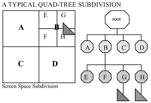
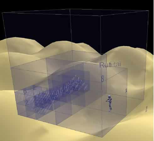
Akenine-Möller and Haines[1] give a solid explanation of several different types of trees, the most easily envisioned of which is a tree that relies on axis-aligned partitioning units, and which are based on tree structures commonly referred to as 'quad-trees' or 'oct-trees' in two or three dimensions, respectively. In the case of the quad-tree, screen space is split once horizontally, and once vertically, dividing the space into four quadrants, most often of equal size (see Figure 2, and for an implementation of the same technique in three dimensions refer to figure 3). For each element to be involved in collision detection, that element is added to any tree-node in which it overlaps. This process is repeated such that any available bin (which on the tree can be thought of as a node) can be further subdivided into four more quadrants (again refer to Figure 1), with the objects being reassigned to which node they now belong to, or in tree-based parlance "pushed down to the lowest possible leaf node".
|
|
Figure 1: Quad-tree axis-aligned scene subdivision, based in part upon Figure 9.4 presented by Akenine-Möller and Haines[1]. |
The second variety of tree commonly found in computer graphics for the purpose of scene subdivision is the Binary Space Partitioning (BSP) Tree. BSP trees can employ the same methodologies used above, but each node on the tree will have at most two children because the tree splits two or three dimensional space on only one axis at a time, and rotates through the axis to produce trees similar to the quad- and oct-trees discussed previously. This has the advantage that the BSP tree can be resorted from nearly any viewpoint, and this technique is commonly used for camera clipping and frustum culling. Note also that BSP trees do not necessarily need to divide the scene along the world axis, and frequently employ a polygon-aligned scheme that differs significantly from the axis-aligned methodologies previously discussed [2].
|
|
Figure 2: Oct-tree axis-aligned scene subdivision. Scene from the MUPPETS system, courtesy of A. Phelps and D. Parks. Copyright © Rochester Institute of Technology 2002-2003. |
Storing Geometry in Tree-Nodes for Quick Retrieval of Neighbors
In some schemes, objects are allowed to register themselves at different levels of the hierarchy for later retrieval; in other schemes an object may simply be registered at multiple end-nodes of the tree. This presents certain problems, particularly in trees that register objects at different levels within the hierarchy, because an object near the center of the scene or that overlaps one of the major axis is checked against the whole scene for collision detection. Ulrich presented a unique solution to this problem, that of loose octrees [3], which use bounding squares 1.5 times larger than half the divisional space and can thus place objects on the major axis squarely within a bounding region.
|
|
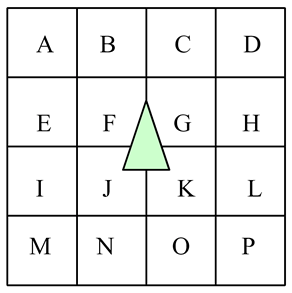
Figure 3: A Predefined Bin System for Spatial Partitioning. |
The authors suggest a much less rigorous implementation than that of a formal tree-based scheme, that of a predefined subdivision that needs only a resorting of the objects into the pre-defined partitions. We refer to this methodology as 'binning' (see figure 3). Using a binning system, the screen is subdivided using AABB methodology into however many appropriate bins, such that the bins are larger, but not significantly larger, than the objects being tested for intersection. (The weakness of such a binning system is that it is relative to the application and requires objects to be roughly 'of a size'. This is appropriate for the authors' use in a game engine, but it should be noted this is not a fully generalized solution.)
A given object may register itself with several such bins, and should register itself with any bin in which it overlaps. This can be accomplished through a very coarse radius sweep, or by a simple point-in-bin style check for each point of an encasing poly-volume. (An encasing poly-volume again relies on the fact that objects are of a size such that they do not span significant number of bins, as overlap is checked but containment is not.) The bins themselves are stored as linear arrays, containing pointers to the objects that are present in the bin on a given frame.
In order to look for collision between objects, an object will first look and see which bins it is currently present in, and then construct a 'possible hit list' of all the other objects that are contained within those same bins. This has the advantage of removing large areas of screen space before the more expensive intersection calculations, but without the overhead of re-partitioning the scene on each frame. Note that this methodology is not as refined as a more complete tree structure, and can introduce significant overhead if a large number of objects are significantly larger than the bin size selected.
Once a suitable level of subdivision has been obtained (generally when the area found is close in size to the object being checked for collision with other artifacts) it is relatively easy, through tree traversal, to obtain a list of objects that are near another object and might possibly collide. For any given object, the object will be registered with a particular node (or nodes) within the tree: by looking at those nodes it is possible to obtain a list of all other objects registered with those nodes, thus excluding most of the search space before any detailed algorithm is called. This is most commonly done for polygons in a three-dimensional scene with regard to clipping and culling, but can also have a large impact in two-dimensional spaces for collision detection, particularly when some later checks for accurate collision are exceedingly expensive, as is the case with intersects implementation in Lingo (when used with the Matte ink type to produce sub-rectangular accuracy).
Movement and Tree Balance
The original use of the tree-based structure, and one that is still common today in computer graphics, is scene/entity or scene/player collision detection. With regard to the general scene, many schemes load the triangles of the level geometry into the scene once, at load time, and then use the tree to produce accurate triangles for either collision detection or rendering purposes. This works relatively easily for scene elements that are largely static, such as the ground in an outdoor environment or the walls and stationary furniture of an office building. (Indeed the use of the quad-tree with regard to landscapes is particularly effective, and can even allow the use of a landscape larger than what can be held in the physical memory of the machine [4]). This technique is less successful, however, on scene elements that are in motion, and least successful on elements that are constantly in motion. This technique is also catastrophic on meshes that are generated procedurally on the fly, which would require re-partitioning on the fly as well [5].
To effectively use such highly mobile elements, it is generally the case that such objects are removed from the tree and re-added on a per-frame or per-update basis. Generally speaking, however, it is not necessary to re-sort all the triangles into individual bins, but rather to only assign the list of triangles in the object the various bins that the bounding volume of the shape overlaps.
In the system described here, for example, each element is assigned its own ploy-volume in two-dimensional space. Any bin that the poly-volume overlaps is assigned a reference to the particular object in question, which would be checked against any other object in the bin, either stationary or mobile. It is important to note that all assignment of bins and list generation should be performed either before all updates transforms to the object hierarchy, or else after all transforms. Odd collision logic can result if objects are added and then checked before others are added or updated, typically resulting in objects that pass through one another if they only overlap for a single update.
The same techniques hold true for more complicated meshes and geometry in 2- and 3-dimensional space. Regardless of implementation, any objects that move throughout the scene have the opportunity to change which area of spatial subdivision in which it would fall. This leads to the final issue with regard to moving objects and collision detection: the so called "quick gun" symptom. If an object is moving at sufficient speed, it is possible that on one frame the objects bounding volume is before or ahead of some object with which it will collide, and on the next frame it has already passed the object with which it might collide. This is commonly seen with paper-thin walls in game environments with characters that can run towards a wall and 'pop-through' it, or who can fall from great distances and fall through the ground plane. One solution to this is to scale the bounding volume of the object by the directional velocity of the object.
Representation of Objects by Simplified Bounding Shape
The previous section made much use of the term 'bounding volume' as a way of quickly describing the area in space that a shape occupies, in either two or three dimensions. In fact, there are several such schemes for producing these volumes [6], all of which have their uses in various places within a collision detection scheme. They are presented here in no particular order other than perhaps conceptual ease, but this should in no way imply that implementation is more difficult in later strategies relative to earlier.
Axis-Aligned Bounding Box (AABB)
The Axis-Aligned Bounding Box (AABB) is probably the easiest to envision. In a two-dimensional space, this represents a rectangular space whose sides are parallel with the x- and y-axis of the world-space. This same idea is extensible to cubic divisions of a three dimensional world-space with the third dimension of the cube running parallel to the z-axis. This is the scheme most commonly used for quad-tree and oct-tree generation and is the scheme used in the 'binning' system described here. Several optimizations have been made in the process of detecting collisions between AABBs, including the popular method proposed by Woo [7], and the Slabs Method [8].
Object Aligned Bounding Box
A complication introduced into the AABB scheme is the rotation of an object. This can be solved by re-generating a new AABB based on the transformed points of the original mesh, but it is just as easy to assign a discrete bounding box or cube to the object in question and allow it to inherit the rotations that are applied to the parent. This new bounding volume is then an Object Aligned Bounding Box (OABB).
Common uses of OABB are for objects that are have considerable length along one axis relative to another, and that rotate. Such an object would, at most rotations, provide a profile that would not directly correspond well to any AABB, and thus a second level is needed. Because of the ease of AABB collision tests, many collision detection methods for OABB schemes involve rotating one or the other of two OABB into an axis-aligned space before checking for collision.
Bounding Circle and Sphere
Another type of bounding volume commonly used is a bounding circle. This is incredibly easy to calculate, as it merely involves taking the pixel of the sprite farthest from the center and using its distance vector as the radius. Collision detection can be solved through basic application of the Pythagorean Theorem [9], with optimizations to avoid the overhead of calculating the square root. Bounding circles can also offer a much better fit to shapes that are roughly circular in nature, avoiding the common "corner" problem of rectangles producing a positive result in collision detection algorithms despite the visual shapes showing no overlap.
This type of bounding volume can be extrapolated to 3D as a simple sphere, which tends to work well for objects that are roundly symmetrical, either spheres in their own-right or things that are almost so. The generation of the sphere can be done algorithmically, as presented by Ritter [10], Welzl [11], and Eberly [12]. Director uses a sphere as the default bounding volume of all objects within the Shockwave-3D® environment, and any collision detections are measured in sphere-sphere collision space. Using a bounding sphere (or a stretched ellipse) works very well and is relatively easy to calculate collision. It is of limited utility, however, in objects that are either more box-like (which is typically the case in wall oriented level geometry), or objects that have significant length along one axis relative to another as length along any axis will by definition increase the radius of the overall sphere, leaving bound empty space around much of the object.
Bounding Mesh
Another solution to the bounding problem is to use a low-res version of the object in question. This is often of lesser performance than the other methods, but with much greater realism in its results. In models constructed of triangles, this refers to the practice of storing a high-res version of the mesh for rendering, but a very low poly-count copy of the mesh for collision detection, and then adding the low-res mesh triangle by triangle to the tree as it moves around the scene. While significantly more computationally intensive than the other methods presented here, the low-poly armatures can be tweaked to offer a very realistic approximation of the higher resolution mesh, and thus offer the best visual illusion.
This idea is extensible to a 'bounding image' in which the pixel size is increased in a coarse approximation of the sprite, and then general purpose image-image collision is employed (see 1.6 for details). Such a scheme would be less precise at the pixel level in the same way that a bounding mesh is less precise at the triangular mesh level, but with similar improvements in performance.
Discrete Oriented Polytope
The final common bounding volume is perhaps the least easily visualized, the Discrete Oriented Polytope or K-DOP (where K is the number of projected faces). To produce a K-DOP, the normals of the slab faces are projected out to produce K- faces of the bounding volume. A more complete discussion of K-DOP bounding volumes is presented by Akenine-Mšller and Haines [6], and is beyond the scope of the simple detection schemes presented here. The system described here is interesting in that it produces bounding shapes very similar to those produces by K-DOP bounding algorithms, although manually rather than algorithmically.
Bounding Volume Collision Detection
Regardless of how the bounding volume is implemented, it is nearly always cheaper to check for the collision of the bounding volumes of two objects than the actual triangular mesh or pixel image of the underlying object. In the case of any two bounding volumes that are both disjoint and convex, this is generally accomplished through the Separating Axis Theorem (SAT). SAT is generally employed in AABB, OOBB, and K-DOP bounding tests for this purpose. It should also be restated that no bounding volume will offer absolutely perfect precision relative to the underlying mesh.
Image-Based Collision Detection
Image or sprite-based collision detection typically comes in two varieties, one of which is highly optimized, and one of which is so slow as to be almost unusable in a scene requiring either great complexity and/or real-time use. The first methodology is to simply use the rectangular bounding volume of the image, and determine if any of the segments that form the rectangle of the first image intersect any of the segments of the second. In essence this is rectangle-rectangle collision detection [13], provided that the images are not rotated (rotated images generally employ a methodology in which they are transcribed into non-rotated recliner volumes). This can be done using a combination of line-line intersection and point-in-rectangle strategies that are relatively trivial, and therefore quick. This is in fact the default methodology used by Macromedia Director for the sprite. intersects function.
The second methodology employed for use in image based collision detection is the use of per-pixel checks on the images themselves to determine overlap. This can be done using a simple matte color (as is the case in Director) or using the alpha value present in images that contain an alpha channel (1-bit generally for GIF images, and up to 16-bits in a 48-bit PNG, the general case being 4 or 8 bits for 16-bit or 32-bit graphics, respectively). The unfortunate side-effect of this type of operation is the absolutely massive number of discrete operations. In theory, in order to perform a pixel accurate image test it would be necessary to check (in the worst case, a non-collision) every single pixel of one of the images against the other. In common practice, the area of overlap between the images is determined using Boolean rectangular subtraction (with many optimizations of similar math) and then the pixels in the overlapping area compared for overlap. Even with such optimizations, however, the number of operations is exponentially larger than other, less accurate, bounding tests, and should be used as a last resort. That Director(r) affords this functionality with ease does not make it the most efficient approach, nor is it often necessary as necessary as is originally thought.
Polygonal Armatures for Approximate Visual Collision
Another option for the detailed collision detection is a polygon armature, which is presented here as an alternative to image-based collision detection described in Image Based Collision Detection above. By representing the collision area as line segments we can approximate the shape of the object while providing a much more accurate collision detection than a simplified bounding shape. This is similar to a K-DOP bounding volume (see previous discussion on Discrete Oriented Polytope) but without the reliance on normal project. This allows the armatire to be of virtually any size or shape, a flexibility that has been exploited to maximum advantage by several game designers in preparing the hit-box of enemies and player controlled vehichles. Once the armature shape is defined, we can use a simple line intersection algorithm to determine whether one armature hits another.
Visual Appeal
One of the key advantages that a polygonal armature offers over a simple bounding volume is the ability to better match the shape of the object in question. An avatar that was significantly longer than it's width would have a bounding sphere that did not accurately describe it's shape (as noted in Bounding Circle and Sphere). A polygon armature, however, can represent these shames with relative ease, given enough points within the polygon to define a coarse outline of the overall avatar. Visually this is very effective in many genres of games where exact, pixel-level, collision detection is not needed. For example, in most shooters the hit-box for the player's ship is significantly smaller than the sprite that represents the ship on-screen. This is a common technique that allows for more frantic gameplay while still mantaining nice visuals.
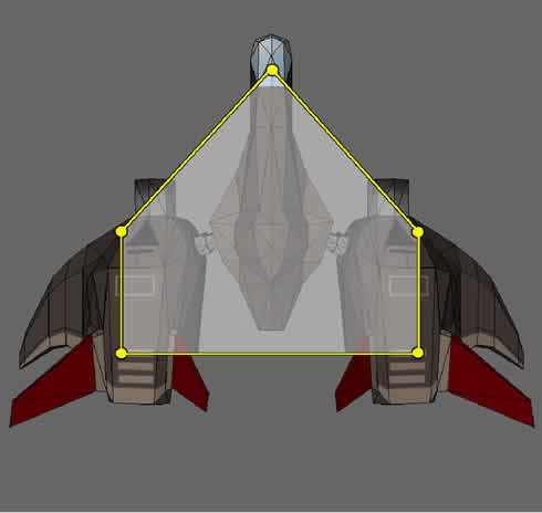
An example of how this would look is presented in Figure 4. In this case the central area of the ship is defined as a hit area but it doesn't cover the whole ship. This provides some nice overlap of object in the game as well as reducing "edge kills" that can feel leave the player feeling cheated. In situations that require more precise collision, the definition of the bounding polygon can be increased and reworked to more closely match the sillouette of the underlying sprite. This is fully adaptable to 3D models as well as sprites, provided that the armature can be projected onto the viewing plane in such a way that it still representes the edge of the model. In situations where the camera employes orthographic projection this is a simple scale: a more complex projection would be required for perspective projection camera support.
|
|
Figure 4. A polygon armature for detailed collision detection. |
Collision Detection through Line Segment Intersection
The hit region from the example in Figure 4 is defined in memory by 5 vector points. These points are translated and rotated as necessary on every frame to stay in sync with the visual representation of our character. Their location can then be used, on a per point basis, to place the object into the appropriate bins (see discussion of the 'binning system in Storing Scene Geometry in Tree-Nodes for Quick Retrieval of Neighbors). Once a possible collision is detected, a simple iteration through the points in each object, in sequence, produces discrete line segments describing the polygon. These line segments are then tested for overlap, and if any overlaps are found the object are said to collide.
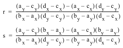
The equation that describes line segment intersection is an interesting one (see Figure 5), and one that presents many subtle optimizations. The equation describes two line segments, denoted as A-B and C-D, in which A,B,C, and D represent points in Cartesian coordinate space (x,y with positive x moving to the right and positive y moving towards the top). These values can be modified as necessary to account for the inversion of screen space and/or other coordinate systems as desired.
|
|
Figure 5: Line segment intersection where the point of intersection is not needed. If 0<=r<=1 and 0<=s<=1 then the segments intersect. |
First, it should be noted that the denominators of both equations are identical, and thus can be computed only once for both equations. Additionally, if the denominator equals zero, then the lines are parallel and do not formally intersect, and the any check for collision detection can return false. (This runs the risk of the lines in fact being co-incident, but in such cases another two segments of the polygon will return the overlap). Antonio [14] presents several optimizations to any implementation of this algorithm, including the denominator check as well as several other strategies to quickly throw out line segment intersection without computing the remainder of the calculations. It should also be noted that the equation above checks solely for intersection, it does not pertain to the issue of one bounding shape existing completely inside another. A complete bounding check would need to also account for point-in-poly collision detection, thus determining if one larger object completely contained another. Haines [15] offers several strategies for this, as does Eberly [16]. The authors have managed to avoid this scenario by again using objects that are roughly similar in size specific to the game environment in which the algorithms are implemented: it is recommended that any generic implementation also allow for containment checks in addition to intersection.
Programmatic Implementation
In the course of implementing these algorithms, several optimization techniques were used to produce a fast, reliable collision detection scheme. First, screen space was divided into discrete bins as previously discussed. Next, each object was assigned a list of untransformed vertices that comprised the bounding shape for the individual models. These vertices are stored as vectors describing the position of the point relative to the center of the model (i.e. the model center is equal to point(0,0) in Cartesian coordinate space). The vertices were defined in 3D Studio Max® at author time directly on top of the models themselves. These points were then exported as custom user-data through the Shockwave 3D exporter and read into Lingo lists using the do command to convert from the user-data string to a list.
After the points are obtained, they go through a process every frame whereby they are rotated to match the rotation of the model, and moved to match the position of the model in screen coordinate space. This presented a significant speed problem because the rotation of the points introduced several sin and cosine operations (see Figure 6), each of which is exceedingly slow. To counteract this, a table of pre-determined sin/cosine values is computed at startup for each integer in the range of 1-360, where zero is treated as 360 degrees (see Figure 7). Floating point angles obtained from the Shockwave 3D environment are rounded to the nearest integer, which because it is reexamined each frame does not introduce significant rounding error.

|
|
Figure 6: Equation describing rotation of a two-dimensional point around the origin in Cartesian space where [x' y'] describes the position of [x y] |
--generate sin / cos lookup tables.
D3D_WORLD[#g_aSin] = []
D3D_WORLD[#g_aCos] = []
repeat with iCounter = 1 to 360
D3D_WORLD[#g_aSin][iCounter] = \
sin(iCounter * D3D_WORLD[#g_fDegrad])
D3D_WORLD[#g_aCos][iCounter] = \
cos(iCounter * D3D_WORLD[#g_fDegrad])
end repeat
on ghRotateVectorShape( a_aVectorShape, a_iDegrees )
aTempVectorShape = a_aVectorShape.duplicate()
aTransformedVectorShape = []
repeat with iCounter = 1 to \
aTempVectorShape.count
vCurVec = aTempVectorShape[iCounter]
fX=vCurVec[1]*D3D_WORLD[#g_aCos][a_iDegrees] - vCurVec[3]*D3D_WORLD[#g_aSin][a_iDegrees]
fZ=vCurVec[1]*D3D_WORLD[#g_aSin][a_iDegrees] + vCurVec[3]*D3D_WORLD[#g_aCos][a_iDegrees]
aTransformedVectorShape[iCounter] = vector(fX, 0, fZ)
end repeat
Figure 7: Code listing for creation of a sin/cos startup table, called from the Startmovie event, and ghRotateVectorShape global handler that uses the pre-generated table.
After the points are rotated and transformed to their screen coordinates, each point is checked to see which bin it is in, and a reference to the object is placed in each bin in which a point falls. This process is repeated for each of three types of entities: enemy ships, enemy bullets, and player bullets, each of which is stored in its own list inside the bin.
The player's ship then begins collision detection by getting a list of which enemy ships and which enemy bullets are present in the bins that the player ship overlaps. The player ship then checks its own bounding shape against the bounding shape for these objects using the code in Figure 8.
--bounding checks to stay within list length
on ghGetNextIndex a_iIndex, a_aListCount/p>
if a_iIndex > a_aListCount then
a_iIndex = 1
else
a_iIndex = a_iIndex
end if
return a_iIndex
end ghGetNextIndex
--check for collision between two poly objects
on ghCheckForCollision(a_oPolyA, a_oPolyB)
bIntersects = void --eventual result
iPolyACount = a_oPolyA.p_aTransformedVertexList.count
iPolyBCount = a_oPolyB.p_aTransformedVertexList.count
--lets try this first with line intersection...
repeat with iCounter1 = 1 to iPolyACount
repeat with iCounter2 = 1 to iPolyBCount
bIntersects = ghCheckLineIntersection( \
a_oPolyA.p_aTransformedVertexList[ \
ghGetNextIndex(iCounter1, \
iPolyACount) ],\
a_oPolyA.p_aTransformedVertexList[ \
ghGetNextIndex(iCounter1 + 1, \
iPolyACount) ], \
a_oPolyB.p_aTransformedVertexList[ \
ghGetNextIndex(iCounter2, \
iPolyBCount)],\
a_oPolyB.p_aTransformedVertexList[ \
ghGetNextIndex(iCounter2 + 1, \
iPolyBCount)])
if bIntersects then return TRUE
end repeat
end repeat
return FALSE
end ghCheckForCollision
--takes 4 points describing two line segments
on ghCheckLineIntersection a_ptA, a_ptB, a_ptC, a_ptD
f =((a_ptB[1]-a_ptA[1])*(a_ptD[3]-a_ptC[3])- \
(a_ptB[3]-a_ptA[3])*(a_ptD[1]-a_ptC[1]))
--parallel or co-incident
if f = 0 then return FALSE
d=((a_ptA[3]-a_ptC[3])*(a_ptD[1]-a_ptC[1])- \
(a_ptA[1]-a_ptC[1])*(a_ptD[3]-a_ptC[3]))
if(f>0) then --/* alpha tests*/
if(d<0 or d>f) then
return FALSE
end if
else
if(d>0 or d<f) then
return FALSE
end if
end if
e=((a_ptA[3]-a_ptC[3])*(a_ptB[1]-a_ptA[1])- \
(a_ptA[1]-a_ptC[1])*(a_ptB[3]-a_ptA[3]))
if(f>0) then --/* beta tests*/
if(e<0 or e>f) then
return FALSE
end if
else
if(e>0 or e<f) then
return FALSE
end if
end if
return TRUE
end ghCheckLineIntersection
Figure 8: Lingo code implementation of poly-poly collision detection.
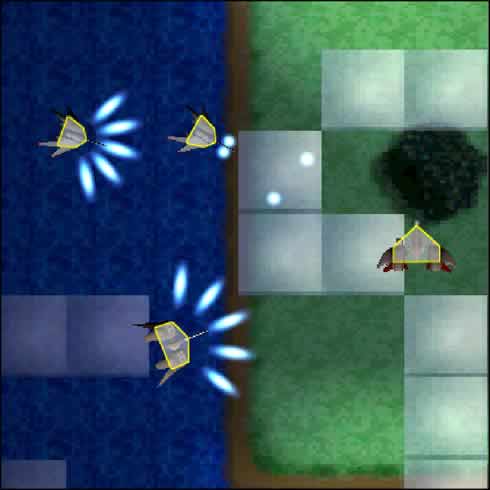
In the code presented above, a poly object has as a property its transformed points as a list. The global functions loop through the points of the first poly creating line segments A-B, B-C, C-D, etc and comparing these segments to each segment constructed from the second poly. The ghCheckForCollision and the ghGetNextIndex handlers are used as wrappers to produce the correct line segments for collision checks, the meat of collision detection is contained in the ghCheckLineIntersection handler, which is an implementation of the mathematical equation presented in Figure 5, with some of the optimizations presented by Antonio [14] implemented in Lingo. As soon as a collision is detected, the function returns true and the game logic can take appropriate action for intersection. After the player is checked for collision against the enemy ships and bullets, the enemies are checked against the player's weapon objects. A screenshot of only ship-ship collision detection using this methodology is presented in Figure 9.
|
|
Figure 9: Ship-Ship collision detection using polygonal armatures in a game engine. Image taken from the Broadsword project, copyright © A. Phelps and A. Cloutier, Rochester Institute of Technology 2003. |
Conclusions
Multi-tiered approaches that incorporate trees, data simplification, and mathematical tests as opposed to pixel based imaging are significantly faster than image-image comparisons. In addition, such measures can be extrapolated into environments in which image-image collision is not readily available, such as a three-dimensional environment viewed through orthographic projection. Additionally, when used in game environments, the use of polygon armatures for collision detection is especially advantageous as it offers designers and play-testers control over the size of the hit-box on various elements within the game as a tunable feature. Future work would likely incorporate the use of other bounding shapes and checks such as spheres and discrete triangles to further minimize the number of checks and calls performed on a per-frame basis, and to further push the expensive collision-detection methodologies further down the chain, thus allowing for faster frame rates and more engine cycles to devote to other tasks.
All colorized Lingo code samples have been processed by Dave Mennenoh's brilliant HTMLingo Xtra, available from his site at http://www.crackconspiracy.com/~davem/
Copyright 1997-2026, Director Online. Article content copyright by respective authors.