Simulating Water with Shockwave 3D
October 25, 2004
by Andrew M. Phelps
Abstract
This article outlines the process of creating a water simulation with semi-realistic properties for use in a typical game engine or other real-time 3D environment. Water simulation is broken down into three major areas: wave propagation, refraction, and reflection. Also discussed are additional solutions for multi-texturing and tiling of the textures needed to produce the simulation, as well as discussion of a technique to incorporate a projection into texture space to simulate a cubic container such as a pool or trough without the underlying geometry.
An example of the simulation is provided using a Shockwave3D implementation. This file is written in the Lingo language for backwards compatibility only: it is wholly capable of being ported to the Javascript-like syntax in DMX 2004. A screenshot of the running simulation is provided in Figure 1:
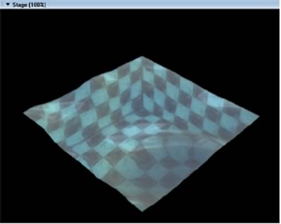
Figure 1: Water simulation with projective texturing, refraction, reflection, and secondary texture blending - #OpenGL renderer.
Download the source file for this movie as a ZIP archive (~900K).
1 WAVE GENERATION & PROPOGATION
There are several available methodologies to approximate wave propagation across a surface. There appear to be, upon brief literature review, three major approaches to wave propagation, each of which is suitable and believable in certain contexts. These are sinusoidal manipulation of a heightfield, manipulation of a heightfield based on recursive noise functions (Perlin noise and/or some other suitable variation), and direct copy of values in a two-dimensional array based on height values in the previous frame. TOP
1.1 SINUSOIDAL MANIPULATIONThe first of these techniques, sinusoidal manipulation, is fairly straightforward. Time (t) is calculated per-frame, and a height value is constructed for each vertex of a height field based on (t) length along a plot of the sine function. Thus for each value (t) a height value is plotted long the x- and y-axis. If the viewer is of sufficient distance from the water, this undulating pattern can be portrayed simply by an animated bump-map on the surface [1]. TOP
Some other variations on this methodology call for varying offsets in sin() along the y-axis relative to x, or for modulation of several sine waves together at differing intervals [2][3]. Still others call for random variations in (t) to produce irregular ripple effects. The weakness of this effect (when unmodified) is relatively apparent: the water feels too regular, and the waves do not interact with the environment [4]. Nonetheless, with careful manipulation and mapping implementations, this technique can look very convincing. It is also possible to add specific water droplets or waves using sprite-overlay techniques, instead of simulating them all in the base surface itself [5]. An advanced implementation of sinusoidal water animation is provided by Snook [6], and several other sources. TOP
1.2 NOISE BASED WAVES
The second technique involves layers of noise over several generations. Patterns of ripples and waves can be created by summing up band-limited noise to make texture maps or height-field data representative of waveforms [7][8]. These layers are then animated to produce ripple effects based on a time-based strategy very similar to that used when dealing with sinusoidal animation. TOP
An advantage of both this and the previous technique that is worth noting is that they both, unlike the following technique, can be made seamlessly tileable with very little effort. Any square patch of water can be placed seamlessly next to another, and waves will appear to propagate across the two of them, provided that their usage of either sin() or the noise() functions are in synch. The disadvantage of this approach is that it is very difficult to animate water emanating from a particular point on the surface, such as would occur from a splash or droplet. TOP
1.3 ARRAY BASED WAVES
1.3.1 Array Construction
The final seemingly major methodology for wave generation and propagation is the so-called "array-based" approach. This method creates two 2-dimensional arrays in which to store height values for the water field (as a point of optimization, it is often better to create one-dimensional arrays and simulate 2D by using x and y offsets into the index lookup). The sample file here uses the algorithm presented by Mason McCusky in his test on special effects [9], although several implementations of this approach are similar. The two arrays, which can be thought of as oldWater and newWater, are populated with an initial height value. For simplicity, the demo program uses zero as the initial value, although it is very feasible to 'pre-seed' the wave field by providing initial values. Every frame, the a copy of the oldWater array is stored, the newWater array is dumped into the old, and the newWater array is replaced with a copy of the oldWater array, as shown in figure 2. This will have direct ramification once one of the values is non-zero inside the array, and once the arrays are 'processed' before being copied. TOP
-- cycle the arrays
-------------------------------------------
aTemp = D3D_WORLD[#g_aOldwater]
D3D_WORLD[#g_aOldwater] =
D3D_WORLD[#g_aNewwater].duplicate()
D3D_WORLD[#g_aNewwater] = aTemp
Figure 2: Managing exchange between old and new water arrays per-frame.
1.3.2 Wave Propagation
Once this system is in place, the trick to creating waves is then two-fold. The first is to choose a point, or set of points, on the oldWater array, and assign a non-zero height to the element in that position. This creates a 'spike' or a 'dent' in the height-field depending on the seed value's sign. TOP
Next, the values from the oldWater array are used to replace values in the newWater array, by sampling the neighbors of the cell in the array in both the vertical and horizontal directions. In simple terms, the value in the newWater array will be the value in the oldWater array modified by the neighboring values in the oldWater array. This created waves that ripple outward concentrically if a single point is used as a seed value, or that undulate as linear waves if a row of seed values is placed into the oldWater array. When the frames cycle, the newWater array is copied into oldWater and the next set of waves is computed from the existing values. TOP
This would produce waves that flow in perpetuity were it not for the fact that each time the average of neighboring values is taken, a dampening factor is applied to reduce the strength of the wave. Depending on this value, the fluid can appear to be highly elastic, or very viscous. Dampening values between 1.05 and 1.5 seem to give the best visual result for standard water, assuming a frame-rate of approximately 30FPS. The algorithm for wave processing is presented in Figure 3. TOP
-- Process Water Arrays
-------------------------------------------
on ghProcessWaterArrays
repeat with cy = 1 to D3D_WORLD[#g_iWaterHeight]
repeat with cx = 1 to D3D_WORLD[#g_iWaterWidth]
x = cx - 1
y = cy - 1
-------------------------------------------
-- add up all the neighboring water values
-------------------------------------------
iXminus1 = x-1
if iXminus1 < 0 then iXminus1 = 0
iXminus2 = x-2
if iXminus2 < 0 then iXminus2 = 0
iYminus1 = y-1
if iYminus1 < 0 then iYminus1 = 0
iYminus2 = y-2
if iYminus2 < 0 then iYminus2 = 0
iXplus1 = x+1
if iXplus1 >= D3D_WORLD[#g_iWaterWidth] then iXplus1 = D3D_WORLD[#g_iWaterWidth] - 1
iXplus2 = x+2
if iXplus2 >= D3D_WORLD[#g_iWaterWidth] then iXplus2 = D3D_WORLD[#g_iWaterWidth] - 1
iYplus1 = y+1
if iYplus1 >= D3D_WORLD[#g_iWaterHeight] then iYplus1 = D3D_WORLD[#g_iWaterHeight] - 1
iYplus2 = y+2
if iYplus2 >= D3D_WORLD[#g_iWaterHeight] then iYplus2 = D3D_WORLD[#g_iWaterHeight] - 1
iValue = D3D_WORLD[#g_aOldwater][((y) * D3D_WORLD[#g_iWaterWidth]) + iXminus1 + 1]
iValue = iValue + D3D_WORLD[#g_aOldwater][((y) * D3D_WORLD[#g_iWaterWidth]) + iXplus1 + 1]
iValue = iValue + D3D_WORLD[#g_aOldwater][((iYminus1) * D3D_WORLD[#g_iWaterWidth]) + x + 1]
iValue = iValue + D3D_WORLD[#g_aOldwater][((iYplus1 ) * D3D_WORLD[#g_iWaterWidth]) + x + 1]
iValue = iValue * 0.5
-------------------------------------------
-- subtract the previous water value
-------------------------------------------
iValue = iValue - D3D_WORLD[#g_aNewwater][(y * D3D_WORLD[#g_iWaterWidth]) + x + 1]
-------------------------------------------
-- dampen it
-------------------------------------------
iValue = integer (float (iValue) / 1.05)
-------------------------------------------
-- store it in the array
-------------------------------------------
D3D_WORLD[#g_aNewwater][(y * D3D_WORLD[#g_iWaterWidth]) + x + 1] = iValue
end repeat
end repeat
end ghProcessWaterArrays
Figure 3: Manipulating water arrays for wave propagation based on previous neighboring values. Lingo implementation of McCusky's more complete example in [9], optimized by reducing the sampling algorithm to a single cell in each direction (as opposed to 2 or 3).
The advantages of array-based waves are based upon their pattern of propagation. It is very easy to produce waves that generate outward in rings from a single source, and it is also easy to "bounce" waves off the sides of containers or pools, as the edges of the array naturally produce this effect when using the array oriented methodology. The disadvantages of this approach are the long calculation time for the processWaterArrays() function, and the memory overhead of storing two height-maps. While the resolution in the demonstration application (a 14x14 grid) can calculate relatively quickly on modern hardware, this technique is not truly scalable to high resolution meshes at interactive frame-rates. TOP
It should be noted also that the geometry used for the water in this demo is not optimal for the wave generation method selected. For waves using array-based approaches, and in particular attempting to do wave "rings", the standard triangle "patch" where all the triangles present their diagonals in the same facing direction will introduce artifacts into the ripple pattern. Figure 4 presents the standard mesh generation, and an optimized mesh for correct waveform representation. TOP
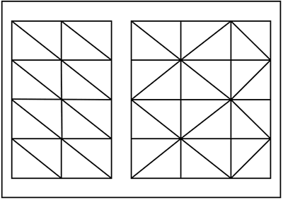
Figure 4: Non-optimal (left) and optimized (right) triangle interlay patterns for water mesh to be used with droplet based wave forms and array-based propagation.
Finally, it is possible, and sometimes desirable, to calculate a low-resolution water array for use with a higher resolution mesh. This can have the advantage of processing the water arrays very quickly, but controlling a mesh of greater resolution, which can therefore look smoother onscreen. This has the effect of "rounding" or "smoothing" the waves, as the mesh vertices that fall in-between the points in the water arrays generally take the weighted average of the two closest points along the x- and y-axis. In this way, the water array can be thought of as a 'control mesh' relative to the actual surface, in a similar manner to the #meshDeform modifier in the Shockwave3D environment. TOP
2 REFRACTION
2.1 SURFACES AND REFRACTIVE RAY CALCULATION
The basic "look and feel" of water (or for that manner any transparent liquid) comes from a combination of its refractive and reflective properties. Refraction is a recognition of the fact that as light enters the surface of the liquid, it is bent, or refracted, before reaching the bottom of the container that holds the liquid. Several approaches for simulating this physical phenomenon exist in computer graphics, the most recent of which focus on using a combination of vertex and pixel shaded techniques to calculate the offset, or refraction, between the point at which light strikes a surface, and where on the bottom of the container the light would land. TOP
The physics formulas for light bending can be significantly involved. A brief summation (and one that ignores internal currents and movement's of a 3-dimensional body of water) is Snell's Law. This theorem describes the two environments that the light passes through (the air and then the water) as each having an index of refraction n. For a perfect vacuum, n = 1.000. Water is generally in the range of n = 1.3333. For a completely smooth surface, the calculation of Snell's Law can be computed using the formula in Fig 5: TOP
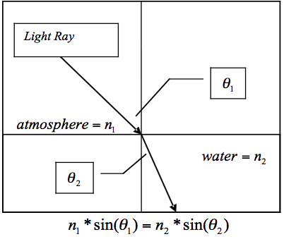
Figure 5: Basic formula of Snell's Law, for light traveling between two surfaces with differing refractive properties.
Using this representation falls short, however, in computing a convoluted surface. Instead, the approach that Vlachos and Mitchell implement in their construction of a water simulation [10] rotates the axis around which the angles are calculated to be planar with the normal of the surface at the point of intersection. This is in fact a practical matter that most such simulations implement. Thus, is not the angle of incidence from the world y-axis, but rather the angle between the eye-vector of the viewer and the normal of the water surface for that particular vertex (or pixel). This forms the basis of computing the refracted ray from the incoming ray between intersection and viewer. This is implemented in the code presented in figure 6: TOP
-- compute camera view
--------------------------------------
VectCamPos = pSprite.camera.transform.position
vertex_current = lWaterVertex[cnt]
camera_ray = VectCamPos - vertex_current
camera_ray = camera_ray.getnormalized()
tmpf = 1.0 / float (sqrt (camera_ray.x * camera_ray.x + camera_ray.y * camera_ray.y + camera_ray.z * camera_ray.z))
camera_ray.x = (camera_ray.x * tmpf)
camera_ray.y = (camera_ray.y * tmpf)
camera_ray.z = (camera_ray.z * tmpf)
camera_ray = camera_ray.getNormalized()
--------------------------------------
-- compute N.I
--------------------------------------
tmpf = vertex_normal.x * camera_ray.x + vertex_normal.y * camera_ray.y + vertex_normal.z*camera_ray.z
tmpf2 = 1.0 - ((0.5625) * (1.0 - (tmpf * tmpf)))
tmpf2 = float(sqrt(tmpf2))
tmpf2 = (0.75*tmpf) - tmpf2
norm = vector(0,0,0)
norm.x = (tmpf2*vertex_normal.x) - (0.75*camera_ray.x)
norm.y = (tmpf2*vertex_normal.y) - (0.75*camera_ray.y)
norm.z = (tmpf2*vertex_normal.z) - (0.75*camera_ray.z)
tmpf2 = 1.0 / float(sqrt(norm.x * norm.x + norm.y*norm.y + norm.z*norm.z))
norm.x = norm.x*tmpf2
norm.y = norm.y*tmpf2
norm.z = norm.z*tmpf2
--------------------------------------
-- point on surface
--------------------------------------
mInc =1.0/((D3D_WORLD[#g_iWATERWIDTH]) -1.0)
nInc=1.0/((D3D_WORLD[#g_iWATERHEIGHT]) -1.0)
tmpv = vector(0,0,0)
tmpv.x = ((j*mInc)*0.998+0.001) * D3D_WORLD[#g_fWaterAspect]
tmpv.y = (i*nInc)*0.998+0.001
tmpv.z = 0.0
Figure 6: Implementation of Snell's Law on a per-vertex basis. Adapted from C/C++ source code by Vlachos and Mitchell in [10].
While this implementation is correct, it is computationally intensive. It is necessary to perform these steps if projected texturing is desired, as the calculation of N.I is particularly critical. For implementations that aren't trying to simulate a box-style container, and are only concerned with the illusion of water overtop of a flat floor texture, significant optimizations can be made, as noted by Anton Pieter van Grootel [11]. A substantially simplified implementation using this approach is presented in Figure 7: TOP
refracted_ray = refracted_ray.getnormalized()
final_depth = pInitialDepth + (vertex_current.y - D3D_WORLD[#g_aNewwater][(i) * D3D_WORLD[#g_iWATERWIDTH] + j + 1])
t = final_depth / float(refracted_ray.y)
map_x = vertex_current.x + refracted_ray.x*t
map_z = vertex_current.z + refracted_ray.z*t
texCoord[1] = (map_x - D3D_WORLD[#g_fXI]) * (D3D_WORLD[#g_fInterpolationFactorX] / (1.000 / D3D_WORLD[#g_fTexRepeatU]))
texCoord[2] = (map_z - D3D_WORLD[#g_fZE]) * (D3D_WORLD[#g_fInterpolationFactorZ] / (1.000/D3D_WORLD[#g_fTexRepeatV]))
Figure 7: Implementation of Snell's Law on a per-vertex basis. Adapted from source code by Anton Pieter van Grootel in [11].
Note here that we are not technically calculating Snell's Law: van Grootel has interestingly noted that a quick approximation of the formal is to use refracted_ray = -(vertex_normal * refraction_coeff + camera_ray), where refraction_coeff is just a scalar, thereby faking Snell's law without the overhead of trigonometry. This greatly simplifies the necessary calculations, but does not provide enough information to simulate the sides of a container in map coordinate space in and of itself. Still, the effect is almost as compelling at significantly reduced computational intensity. TOP
2.2 TEXTURE MAPPING AND COORDINATE LOOKUPS
The previous figure also featured the base calculation of texture coordinates for each vertex, offset by bending of the refractive ray. For each vertex, the algorithm computes a texCoord consisting of a u/v pair. It should be noted that this author has slightly modified van Grootel's original implementation to account for a repeating texture across the bottom of the water surface. In the demo file, users can set D3D_WORLD[#g_bUseProjectiveTexturing] to false to see this technique in action. TOP
2.3 SIMULATION OF BASIC CONTAINERS
The above technique, however, does not account for perspective correction in the texture lookup. More correctly, it does not account for the refractive rays to strike the sides of a container rather than the bottom. For liquids in simple containers, such as a pool, this is a substantial shortcoming. TOP
Using information from the original work by Vlachos and Mitchell, it is entirely possible to re-implement their solution in Shockwave3D. Their solution to this issue revolves around the concept that the refracted ray will hit one of 5 sides of a container: one of the four walls, or the floor, and then shifts the texture coordinate lookup accordingly. Thus, things that hit the floor map to the center area of a texture, and the walls to the outlying areas. Camera position and surface normal (through calculation of N.I) is used to only show sides that would be visible from that angle. Thus, this approach simulates the look of a 3D container using texture lookups, rather than geometry. While not as detailed as a full geometric mesh, this technique can produce very realistic results, with only minor imperfections. The algorithm for determining wall intersection and u/v coordinate lookup is presented in Figure 8. TOP
-- point on surface
-------------------------------------------
mInc = 1.0 / ((D3D_WORLD[#g_iWATERHEIGHT]) - 1.0)
nInc = 1.0 / ((D3D_WORLD[#g_iWATERHEIGHT]) - 1.0)
tmpv = vector (0, 0, 0)
tmpv.x = ((j * mInc) * 0.998 + 0.001) * D3D_WORLD[#g_fWaterAspect]
tmpv.y = (i * nInc) * 0.998 + 0.001
tmpv.z = 0.0
-------------------------------------------
-- Intersect with left plane (-1 0 0 0)
-------------------------------------------
if (norm.x = 0.0) then --Parallel to plane
dist[1] = the maxInteger
else
dist[1] = (tmpv.x) / (-norm.x)
end if
if (dist[1] < 0.0) then --If behind ray
dist[1] = the maxInteger
end if
-------------------------------------------
-- Intersect with right plane (-1 0 0 -1)
-------------------------------------------
if (norm.x = 0.0) then --Parallel to plane
dist[2] = the maxInteger
else
dist[2] = (-D3D_WORLD[#g_fWaterAspect] + tmpv.x) / (-norm.x)
end if
if (dist[2] < 0.0) then --If behind ray
dist[2] = the maxInteger
end if
-------------------------------------------
-- Intersect with bottom plane (0 -1 0 0)
-------------------------------------------
if (norm.z = 0.0) then --Parallel to plane
dist[3] = the maxInteger
else
dist[3] = (tmpv.y) / (-norm.z)
end if
if (dist[3] < 0.0) then --If behind ray
dist[3] = the maxInteger
end if
-------------------------------------------
-- Intersect with top plane (0 -1 0 -1)
-------------------------------------------
if (norm.z = 0.0) then --Parallel to plane
dist[4] = the maxInteger
else
dist[4] = (-1.0 + tmpv.y) / (-norm.z)
end if
if (dist[4] < 0.0) then --If behind ray
dist[4] = the maxInteger
end if
-------------------------------------------
-- Intersect with floor plane (0 0 -1 1)
-------------------------------------------
dist[5] = (D3D_WORLD[#g_fWaterDepth] + tmpv.z) / (-norm.y)
if (dist[5] < 0.0) then --//If behind ray
dist[5] = the maxInteger
end if
-------------------------------------------
-- Find closest wall
-------------------------------------------
tmpi = 1
if (dist[2] < dist[tmpi]) then
tmpi = 2
end if
if (dist[3] < dist[tmpi]) then
tmpi = 3
end if
if (dist[4] < dist[tmpi]) then
tmpi = 4
end if
if (dist[5] < dist[tmpi]) then
tmpi = 5
end if
-------------------------------------------
-- Floor
-------------------------------------------
if (tmpi = 5) then
tmpv.x = tmpv.x + norm.x*dist[tmpi]
tmpv.y = tmpv.y + norm.z*dist[tmpi]
tmpv.z = tmpv.z + norm.y*dist[tmpi]
-------------------------------------------
-- Use y and z to figure out texture cords
-------------------------------------------
texCoord[1] = tmpv.x / D3D_WORLD[#g_fWaterAspect]*0.5 + 0.25
texCoord[2] = tmpv.y * 0.5 + 0.25
-------------------------------------------
-- Left Wall
-------------------------------------------
else if (tmpi = 1) then
tmpv.x = tmpv.x + norm.x * dist[tmpi]
tmpv.y = tmpv.y + norm.z * dist[tmpi]
tmpv.z = norm.y * dist[tmpi]
-------------------------------------------
-- Use y and z to figure out texture coords
-------------------------------------------
texCoord[1] = -0.25*tmpv.z / D3D_WORLD[#g_fWaterDepth]
texCoord[2] = ((texCoord[1])) + (tmpv.y * ((1.0 - 2.0 * texCoord[1])))
-------------------------------------------
-- Right Wall
-------------------------------------------
else if (tmpi = 2) then
tmpv.x = tmpv.x + norm.x*dist[tmpi]
tmpv.y = tmpv.y + norm.z*dist[tmpi]
tmpv.z = norm.y*dist[tmpi]
-------------------------------------------
-- Use y and z to figure out texture coords
-------------------------------------------
texCoord[1] = -0.25*tmpv.z / D3D_WORLD[#g_fWaterDepth]
texCoord[2] = ((texCoord[1])) + (tmpv.y * ((1.0 - 2.0 * texCoord[1])))
texCoord[1] = 1.0 - texCoord[1]
-------------------------------------------
-- Bottom Wall
-------------------------------------------
else if (tmpi = 3) then
tmpv.x = tmpv.x + norm.x*dist[tmpi]
tmpv.y = tmpv.y + norm.z*dist[tmpi]
tmpv.z = norm.y*dist[tmpi]
-------------------------------------------
-- Use x and z to figure out texture coords
-------------------------------------------
texCoord[2] = -0.25*tmpv.z/ D3D_WORLD[#g_fWaterDepth]
texCoord[1] = ((texCoord[2])) + (tmpv.x / D3D_WORLD[#g_fWaterAspect]* ((1.0 - 2.0 * texCoord[2])))
-------------------------------------------
-- Top Wall
-------------------------------------------
else if (tmpi = 4) then
tmpv.x = tmpv.x + norm.x*dist[tmpi]
tmpv.y = tmpv.y + norm.z*dist[tmpi]
tmpv.z = norm.y*dist[tmpi]
-------------------------------------------
-- Use x and z to figure out texture coords
-------------------------------------------
texCoord[2] = -0.25*tmpv.z/ D3D_WORLD[#g_fWaterDepth]
texCoord[1] = ((texCoord[2])) + (tmpv.x / D3D_WORLD[#g_fWaterAspect] * ((1.0 - 2.0 * texCoord[2])))
texCoord[2] = 1.0 - texCoord[2]
end if
Figure 8: Implementation of simple container simulation on a per-vertex basis. Adapted from C/C++ source code by Vlachos and Mitchell in [10].
3 REFLECTION
3.1 TEXTURE MAP CALCULATION
The second property that any water simulation needs to account for in order to display a semi-realistic looking liquid is reflection. Water not only bends entering light, it also reflects it back towards the viewer. This demo computes reflected light on a per-vertex algorithm, in the same way it does for refraction. The code to generate a u/v pair for reflection is presented in figure 9: TOP
-- reflection
-------------------------------------------
dotCamVertexNormal = camera_ray.dot(vertex_normal)
reflected_ray = 2.0 * dotCamVertexNormal * vertex_normal - camera_ray
reflected_ray = reflected_ray.getnormalized()
texCoord[1] = (reflected_ray.y + 1.0) / 2.0
texCoord[2] = (reflected_ray.y + 1.0) / 2.0
Figure 9: Implementation of reflective texture coordinates. Adapted from source code by Anton Pieter van Grootel in [11].
This manner of texture map calculation greatly perturbs the underlying texture (and this solution is further modified by the author to use the y coordinate for both u and v texture coordinate lookups rather than tying u to either x or z as per the original implementation, which produces a more chaotic effect). The reflective texture is then blended with the original texture as a second texture layer. The exact blend is specified in the D3D_WORLD[ #g_iReflectBlend] variable that is set in the startmovie script. Figure 9 shows the simulation running with a reflect blend level of 100 (totally reflective), 50 (half-and-half blend between reflective and refractive textures), and 0 (no reflection). NOTE: the blending of the texture, with separate texture coordinates is only possible in the Shockwave 3D environment if the underlying mesh is constructed using the undocumented #layers argument to the newMesh() command [12], which specifies the number of texture coordinate layers to assign to the mesh. For this reason, the mesh creation script is modified from its original implementation by Catanese [13]. TOP
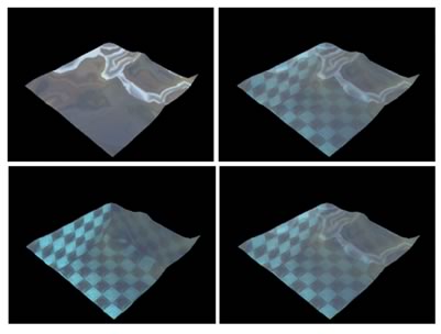
Figure 10: Water with a base refract map and an overlaid reflect map, with reflect at 100% opacity (top-left), 50% opacity (top-right), 0% opacity (bottom-left), and the simulation default of 35% (bottom-right).
3.2 TEXTURE MAP GENERATION
The water demo presented here uses a static reflect map. It would be possible, using a variety of techniques, to use cameras in the 3D scene to take images or snapshots at startup, and to use those images to construct a more complete reflect map of the environment. In engines that support render-to-texture functionality, this can be done in real-time. Using such techniques could add a further element of realism to the reflection map than is presented here, although the chaotic nature of this particular method of texture coordinate calculation may make such gains of negligible value, if the visual impact of more complete reflections is not discernable. TOP
4 2D WAVE TEXTURING
As a final added detail, the water simulation creates a very low-res image that calculates the color of the wave at a given vertex. This is presented as a very performance-friendly way of simulating a Fresnel term, without any of the calculation usually involved in computing such solutions. It must be noted, however that increasing the size of the texture drastically increases its computation time, and images of sufficient size will bring the entire simulation to a halt. By using the texture blurring capabilities on modern graphics hardware, very low-res images can produce acceptable results.
Essentially each of the vertices of the array can also be though of as a pixel in an image. For each vertex, a color is calculated and drawn to an image at that location. This image is then overlaid as a third and final texture to the water in the simulation. Color is calculated in one of two ways, either by using a refract-map technique similar to that presented in [9], or by using a simple height ramp (i.e. based on the y-axis coordinate of the matching vertex). Figure 11 shows sample of this kind of texture at a resolution of 16x16 pixels, for 48 frames. (Note that the images are generally only used as a texture in the 3D world and not written out as images). TOP
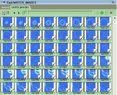
Figure 11: Water textures at 16x16 resolution and color-ramped from blue to white based on vertex height.
5 FUTURE WORK
5.1 CAUSTICS
One area which this simulation completely ignores is the development of a real-time caustics simulation. Such work, like that by Guardado and Sanchez-Crespo [14], could lend another level of realism to the simulation, and further enhance the illusion of light playing across the surface of the water. Imaging solutions could likely be built to approximate the effect without the use of vertex and pixel shaders for use in low-performance environments. TOP
5.2 REFLECT/REFRACT MAPS
The current implementation of a reflect texture and per-vertex refract calculation, while somewhat optimal, is often not as visually appealing as it could be at low mesh resolutions. It is possible that mapping between the vertices using additional textures and blurring would produce more seamless results, and additional tricks with mapping coordinates are certainly possible. This avenue seems promising for further extending the effect without significant overhead: if inter-vertex mapping solutions are found to be optimal, the resolution of the overall mesh could be reduced yet further. TOP
6 CONCLUSION
This demo explores the combination of several current techniques to construct a simulation of realistic water. While the water produced here is visually acceptable, it would be greatly enhanced (and operate significantly faster) through a shading language. However, since many environments still do not support such a language, this implementation may provide a decent alternative until that technology is more widely adopted. This water simulation should provide some insight into how to establish real-time water for other games and virtual worlds that require such a visual effect. TOP
References
[1] Max, N. Carla's Island, animation, ACM SIGGRAPH 81 Video Review, 5, 1981. Referenced in Computer Graphics, Principles and Practice, Second Edition in C. Foley, et. al. Addison-Wesley, Reading, Massachusetts. 1996. RETURN
[2] Isidoro, John, Alex Vlachos and Chris Brennan. "Rendering Ocean Water". 347-357. Direct3D ShaderX: Vertex and Pixel Shader Tips and Tricks. Wolfgang F. Engel, editor. Wordware Publishing, Plano, Texas. 2002. RETURN
[3] Finch, Mark. "Effective Water Simulation from Physical Models". GPU Gems. Randima Fernando, Editor. Addison-Wesley / Nvidia, Boston, Massachusetts. 2004. RETURN
[4] Dalmau, Daniel Sanchez-Crespo. p.644. Core Technologies and Algorithms in Game Programming. New Riders Publishing, Indianapolis, Indiana. 2004. RETURN
[5] Lefebvre, Sylvain. "Drops of Water and Texture Sprites". p.191-206. Shader X2: Shader Programming Tips & Tricks with DirectX 9. Wolfgang F. Engel, editor. Wordware Publishing, Plano, Texas. 2004. RETURN
[6] Snook, G. Real-Time 3D Terrain Engines using C++ and DirectX 9. p274-292. Charles River Media. RETURN
[7] Perlin, K. "An Image Synthesizer" SIGGRAPH 85 287-296. RETURN
[8] Worley, Steven. "Cellular Texturing" p141. Texturing & Modeling: A Procedural Approach. 3rd Edition. Ebert, et. al. Morgan Kauffman, Amsterdam. 2003. RETURN
[9] McCusky, M. P470-475. Special Effects Game Programming with DirectX. The Premier Press Game Development Series. Premier Press, 2002. RETURN
[10] Vlachos, Alex and Jason L. Mitchell. "Refraction Mapping for Liquids in Containers". P. 594-599. Game Programming Gems. Mark DeLoura, Editor. Charles River Media, Rockland, Massachusetts. 2000. RETURN
[11] van Grootel, Anton Pieter. "How to Fake Refraction?". Dir-Games-L Mailing List. University of Georgia. 6/5/2003 Online: http://nuttybar.drama.uga.edu/ pipermail/dir3d-l/2003-June/003415.html RETURN
[12] Leske, Christopher. "Undocumented Feature". Undocumented Lingo. 5/15/2003 Available Online: http://www.director3d.de/2003/05/15.html RETURN
[13] Catanese, Paul. p741-746. Director's Third Dimension: Fundamentals of 3D Programming in Director 8.5. Que, Indianapolis, Indiana. 2002. RETURN
[14] Guardado, Juan and Daniel Sanchez-Crespo. "Rendering Water Caustics". GPU Gems. Randima Fernando, Editor. Addison-Wesley / Nvidia, Boston, Massachusetts. 2004. RETURN
Copyright 1997-2026, Director Online. Article content copyright by respective authors.